
GRID-FORMING E-STATCOM vs SYNCHRONOUS CONDENSER
Two routes to grid stability — and the case for repurposing what we already have

1. The problem we are trying to solve
As coal, gas and large hydro generators retire, three things they used to provide as a free by-product of generation start to disappear from the power system: rotational inertia (which slows down frequency changes), short-circuit current (which makes protection systems work) and a stiff voltage waveform (which inverter-based renewables need to remain stable). Wind, solar PV and battery storage do not naturally provide these services — and as their share of the generation mix grows, the risk of frequency excursions, voltage instability and protection mis-operation grows with them.
Around the world, transmission system operators (TSOs) are being told to procure these services as deliberate, paid-for products rather than expecting them as a side-effect of energy supply. The Australian Energy Market Operator (AEMO) frames this very explicitly: in its 2025 Transition Plan for System Security, it identifies system strength, frequency and inertia, voltage control, and transient and oscillatory stability as the key technical pillars that must be maintained as the synchronous fleet leaves the system. Similar conclusions are being drawn by ENTSO-E members in Europe and by NERC and the ISOs in North America.
Two technologies dominate the conversation about how to fill the gap: the modern grid-forming static compensator — often called an E-STATCOM — and the synchronous condenser. They are sometimes presented as competitors, and sometimes as complements. The reality, as we will see, is more interesting: for inertia, dynamic reactive support and most steady-state services they are functionally equivalent when comparably sized, and the choice between them comes down to short-circuit current, footprint, lead time and cost. This article walks through the dynamic comparison, the practical engineering and commercial differences, and then introduces a third option that is increasingly attractive when both speed and inertia matter: re-using the synchronous machines that are already installed across our grids, with the help of a clutch.
2. What each technology actually is
2.1 The synchronous condenser
A synchronous condenser (often abbreviated SC or sync con) is, mechanically, a synchronous generator with the prime mover removed or disconnected. It spins in synchronism with the grid, but it does not produce active power. It is excited and controlled to absorb or inject reactive power on demand, and — because it is a real rotating mass connected through magnetic coupling to the network — it inherently provides:
• Physical inertia, which slows the rate of change of frequency (RoCoF) following any disturbance;
• Short-circuit current, which boosts the local fault level and keeps protection coordinated;
• A stiff voltage waveform that helps surrounding inverter-based resources remain stable;
• Damping of inter-area and sub-synchronous oscillations through its electromechanical dynamics.
These services are delivered by the laws of physics — no fast control loop is required. A flywheel can be added on the same shaft to multiply the inertia contribution several times over. The technology has been deployed in power systems for more than a century and is well understood by operators, OEMs and protection engineers.
2.2 The E-STATCOM (grid-forming STATCOM)
A conventional STATCOM is a voltage-source converter that exchanges reactive power with the grid through pulse-width-modulated switching. It is fast — sub-cycle response times — and very compact. Historically it has been operated in grid-following mode: it measures the grid voltage and current, then injects reactive current to regulate the local voltage.
An E-STATCOM (sometimes ‘enhanced’ STATCOM, sometimes ‘energy-buffered’ STATCOM, depending on vendor) is the next-generation device. It runs in grid-forming mode, behaving as a voltage source behind a virtual impedance — much closer in character to a synchronous machine than to a current source. With a modest energy buffer (typically a battery, supercapacitor or DC-link capacitor bank sized for seconds rather than minutes), it can also inject and absorb active power for short durations. That extra capability is what unlocks synthetic inertia, fast frequency response and active damping of oscillations from a device that is fundamentally power-electronic.
An E-STATCOM does not have a rotating mass. Its inertia is synthesised by the control system and supplied by its DC-side energy buffer rather than stored in a flywheel. Within the bandwidth and current limits of the converter, however, the active-power response can be controlled to be electromechanically equivalent to that of a synchronous machine — including the inertial response that resists rapid changes in frequency. The size of the energy buffer determines for how long that emulated inertial response can be sustained, and therefore the effective inertia constant the device delivers. The differences between the two technologies are therefore subtler than ‘physical versus synthetic’ — they live mostly in the response to faults and in the engineering of the energy buffer, as the next section makes clear.
3. Dynamic performance — the heart of the comparison
The most important question for a TSO is not ‘can this device provide reactive power?’ — both can. The important question is: how does it behave in the milliseconds and seconds after a disturbance? Figure 1 illustrates the difference using two canonical events: a sudden generation trip (left), and a remote three-phase fault (right). Both scenarios assume the same low-inertia base system; the only thing that changes is whether stability support is added, and which kind.
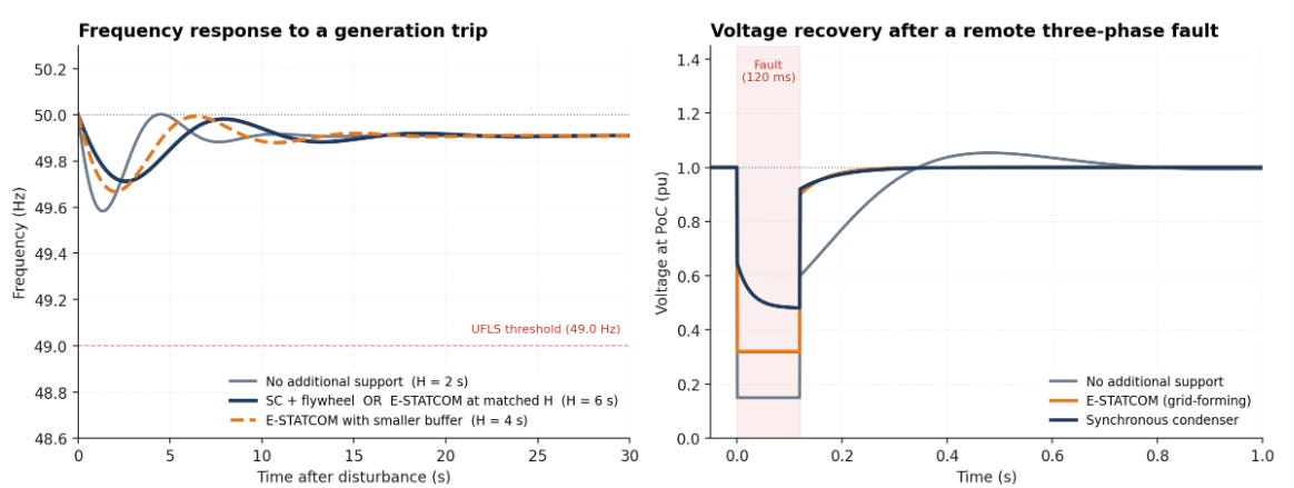
3.1 What the frequency response shows
In the generation-trip case (left panel of Figure 1), all three traces start at 50 Hz and dip when generation is suddenly lost. They also all converge to the same quasi-steady-state frequency once the governor on the surviving synchronous generation has caught up. This is no coincidence: neither the synchronous condenser nor the E-STATCOM produces sustained active power. The post-event frequency is set entirely by the governor / droop characteristic of the rest of the system, so steady-state behaviour is identical regardless of which inertia-providing asset is added. Both technologies act on the transient phase only — and that is where the differences live.
Here is the key point that is often missed in technology comparisons: a properly designed grid-forming E-STATCOM with sufficient DC-link energy (typically a supercapacitor or a small dedicated battery) can deliver a virtual inertia constant equivalent to — or even greater than — that of a synchronous condenser with flywheel. The choice of inertia constant is essentially a design parameter set by the size of the DC-side energy buffer for the converter, just as it is set by the size of the rotating mass for the synchronous condenser. Indicative published values are roughly: H = 1–2 s for a cylindrical-rotor synchronous condenser without flywheel, H = 3–5 s for a salient-pole machine, H = 5–9 s when a flywheel is added, and H = 2–10 s for grid-forming converters depending on the buffer specification. Recent EMT-based comparative studies between grid-forming VSCs with adequate energy buffers and synchronous condensers have shown that the two technologies achieve essentially equivalent inertial response on the seconds timescale when the inertia constants are matched.
Figure 1 illustrates this directly. The grey trace — no additional support, with the system inertia constant left at H = 2 s — shows the steepest initial rate of change of frequency (RoCoF) and the deepest nadir. The navy trace shows the response when system inertia is raised to H = 6 s — and this single curve represents both a synchronous condenser with flywheel and a grid-forming E-STATCOM sized for matched virtual H. The two technologies produce indistinguishable frequency response in this regime: same RoCoF, same nadir, same recovery character. The amber dashed trace shows what happens with a more modestly buffered E-STATCOM (virtual H = 4 s) — an intermediate response, illustrating that inertia is a design parameter the developer can dial in by sizing the energy buffer.
The implication is important. If the system needs more inertia, both technologies can deliver it, and at matched H the dynamic frequency response is the same. The question of which to choose for inertia provision is therefore not a question of capability — it is a question of how the buffer (whether it is a flywheel of steel or a bank of supercapacitors) is best engineered, sized, located, and paid for. The differences live elsewhere — particularly in the response to voltage dips, as the right-hand panel of Figure 1 makes clear.
3.2 What the voltage response shows
The right-hand panel of Figure 1 shows what happens during and after a remote three-phase fault. During the 120 ms fault window, all three voltages collapse, but the differences between the supported cases are striking — and the synchronous condenser holds the residual voltage substantially higher than the E-STATCOM.
This difference comes down to fault-current physics. A 125 MVA synchronous condenser, driven by its sub-transient EMF behind a typical sub-transient reactance of around 0.18 pu, can inject five to six times its rated current into a nearby fault at the instant of fault inception. That is a natural, instantaneous physical response — no control loop is involved. However, this peak contribution does not last: the damper winding currents that produce the sub-transient response decay with a time constant T″d of around 20–40 ms, after which the equivalent impedance rises toward the transient reactance X′d and the residual voltage drops. This is visible in the figure as the downward slope on the navy trace during the fault. Even after this decay, the synchronous condenser’s residual voltage (~0.48 pu) remains substantially above that of the E-STATCOM (~0.32 pu), which is bounded by the current rating of its IGBTs — typically around 1.0–1.2 pu — and provides a constant but more modest voltage support throughout the fault. For surrounding inverter-based plant whose ride-through behaviour depends on the depth of the voltage dip, both the initial peak and the sustained residual are significant.
After the fault clears, the unsupported case shows the slow, oscillatory recovery typical of a weak grid: voltage overshoots and oscillates as the sparse remaining synchronous machines and slow controls hunt for a stable operating point. The E-STATCOM produces the smoothest, fastest recovery — its high-bandwidth control simply pins the voltage to the reference within a few tens of milliseconds. The synchronous condenser sits between the two: a clean recovery with a small, naturally well-damped electromechanical character.
3.3 A side-by-side comparison against grid-forming requirements
The dynamic differences shown above are part of a broader picture. Modern grid-forming specifications — notably AEMO’s voluntary Grid-Forming Specification (2023), the GB Grid Code GC0137 and ENTSO-E’s HPoPEIPS — set out a consistent set of capabilities that a grid-forming asset is expected to provide. Table 1 maps the two technologies against these requirements. The picture that emerges is more nuanced than a straight winner-loser comparison: for inertia, dynamic reactive power, and steady-state services, the two technologies are essentially equivalent when sized comparably. The clear physical difference is in fault-current contribution, which is much larger for the synchronous condenser by virtue of its electromechanical design.

Two structural conclusions emerge from Table 1. First, on most stability services — inertia, reactive power, oscillation damping in the inter-area range, weak-grid voltage support — the two technologies are functionally equivalent when comparably sized. The single clear and material physical difference is in short-circuit current contribution, where the synchronous condenser leads by an order of magnitude. Second, the choice between technologies is therefore primarily an engineering and commercial question — what physical buffer to invest in (rotating mass with bearings, lubrication and a foundation, or DC capacitors / supercapacitors and a converter), and where the asset sits on the cost / lead time / footprint trade-off. That is the subject of the next section.
4. Costs, footprint and lead time — the practical realities
Dynamic performance matters, but so does the engineering, civil and commercial reality of getting kit on the ground.
4.1 New synchronous condensers — the slow, large, expensive baseline
A purpose-built synchronous condenser of around 125 MVA is a substantial piece of rotating plant. It needs a foundation engineered for the rotor mass, a starting system (usually a pony motor or a static frequency converter), an excitation system, lubrication, cooling, an associated transformer, switchgear, and a building. The ARENA / DIgSILENT report on Repurposing Existing Generators as Synchronous Condensers (2023) puts the indicative cost of a new ~125 MVA SC at around AUD 35–40 million, with delivery and installation lead times of 30 months or more from order to commissioning. Crucially, the report flags that lead times are lengthening as international demand grows: the global queue for large rotating machines is competing with the same OEMs that European, Australian and North American TSOs are trying to procure from.
Footprint is also non-trivial. A 125 MVA SC plus its auxiliaries typically occupies the better part of a substation bay — civil works for foundations alone can take six to twelve months of the lead time.
4.2 The E-STATCOM — compact, fast to deliver, but limited at scale
An E-STATCOM is, fundamentally, a power electronic converter housed in a building or in an outdoor enclosure, plus its DC-side energy buffer. There is no rotating mass, no foundation engineering, no cooling water loop, no pony motor. A device of equivalent reactive power rating typically occupies a fraction of the footprint of a synchronous condenser and can be delivered considerably faster — typically in the order of 12 months for the converter package, plus connection works.
The cost picture is more nuanced. Per MVA of reactive power, modern STATCOMs are competitive with — and in some cases cheaper than — new synchronous condensers. But the moment one wants meaningful active-power capability for synthetic inertia or fast frequency response, the energy buffer (battery or supercapacitor) starts to dominate the cost.
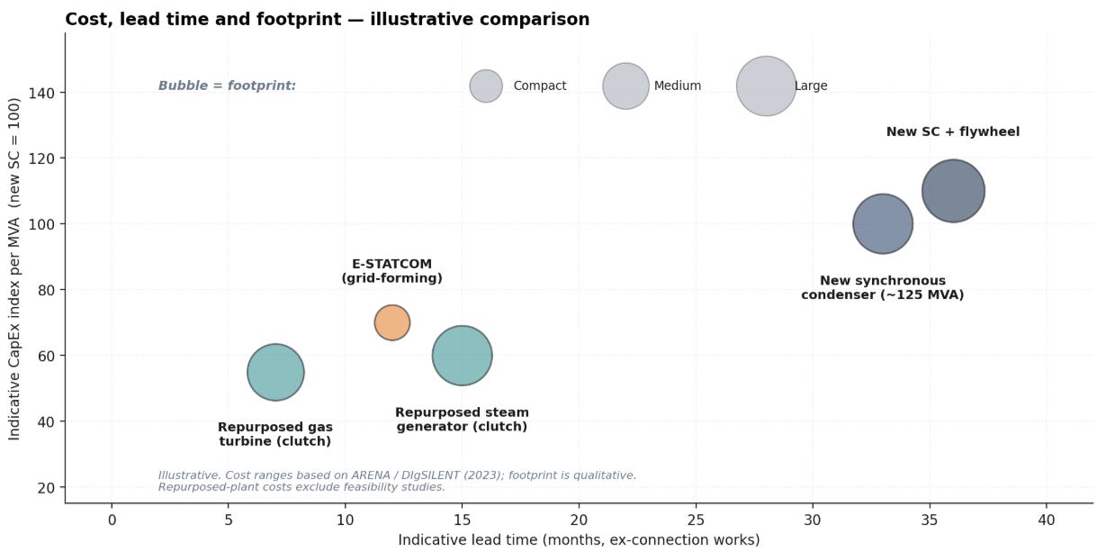
4.3 The trade-off, visualised
Figure 3 places the main options on a single chart of indicative cost (vertical), lead time (horizontal) and footprint (bubble size), with cost figures benchmarked against a new synchronous condenser at index 100. Two things stand out. First, new synchronous condensers — including those with flywheels — are the most expensive and slowest option. Second, the cluster of repurposing options sits in the bottom-left corner: faster, cheaper, larger footprint than an E-STATCOM (because the rotating machine is already installed), but a much smaller marginal civil and equipment investment than building a new sync con from scratch.
5. A third route: Clutch Enabled Synchronous Condensers
If the inertia and short-circuit problem is most acute around the same sites where coal, gas and combined-cycle plant are operating or retiring, then a logical question is: why scrap the synchronous machine? It is already installed, already connected to the grid, already on a foundation, and already inside a substation. What if we kept the generator and disconnected only the prime mover?
This is precisely the concept that SSS Gears has been deploying for more than 60 years across more than 600 installations worldwide — in peaking power plants, in synchronous condenser conversions, and increasingly in repurposed thermal generators. The enabling technology is a synchronising, self-shifting (SSS) clutch: a mechanical device installed between the prime mover and the generator that engages automatically when the input shaft speed matches the output speed, and disengages automatically when the input slows down.
5.1 The concept in one diagram
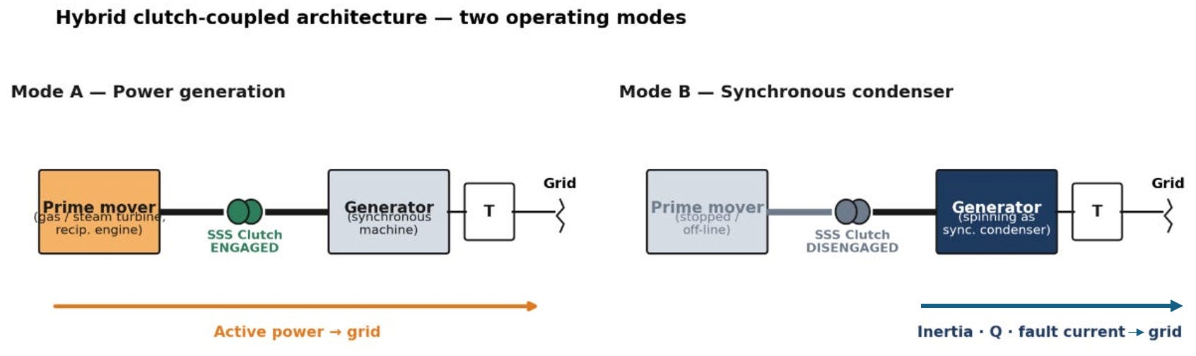
The architecture supports two operating modes. In Mode A, the prime mover (a gas turbine, steam turbine, reciprocating engine, or expander) drives the generator and active power flows to the grid. When market conditions or system security dictates that active power is no longer needed, the prime mover is shut down. The clutch automatically disengages, and the generator is held at synchronous speed by the grid itself, drawing only the small amount of motoring power needed to overcome windage and friction losses. In this Mode B it provides exactly the services a stand-alone synchronous condenser would provide: inertia, short-circuit current, reactive power and a stiff voltage waveform — without giving up the option of returning to active-power generation when needed.
5.2 Three main deployment patterns
There are three distinct ways the clutch concept is being deployed in practice today, each addressing a slightly different commercial and engineering opportunity.
Pattern 1 — New-build power plant with clutch-coupled grid stability services. When a new gas turbine, reciprocating engine or expander is specified, an SSS Clutch can be included from the outset between the prime mover and the generator. The plant earns revenue as a peaker when the market needs energy, and provides system strength and inertia as a synchronous condenser the rest of the time. In jurisdictions that pay separately for grid stability services, the two revenue streams can be stacked. In Great Britain, for example, NESO has procured grid stability through its Stability Market auctions, and clutched solutions have been successful in both Round 1 and Round 2 of the Mid-Term Y-1 auctions. On that basis, the payback period from stability revenues alone for adding an SSS Clutch to a new-build power plant can be under 12 months. This is also the operating model that AEMO highlights in its 2025 Transition Plan for System Security as ‘hybrid gas turbine–synchronous condenser’.
The requirement for peaking plant as active power security, particularly for longer term shortfalls, is likely to increase. As battery storage increases peaking plant active generation profile will become less certain and more ‘peaky’. Giving such plant a dual role with one grid connection is both technically robust and cost effective.
Pattern 2 — Retrofitting a clutch between an existing driver and its generator. An SSS Clutch can be installed between an existing prime mover and its original generator, allowing the asset to switch flexibly between active-power generation and synchronous condenser duty without replacing either the turbine or the generator. The Townsville Power Station in Queensland, Australia is a recent example: Siemens Energy retrofitted a 280T SSS Clutch to convert a Siemens SGT5-2000E gas turbine and generator (originally installed in the late 1990s) into a Hybrid Rotating Grid Stabilizer. The retrofit was selected after Powerlink considered eight alternative options to address minimum fault level and system strength shortfalls, and was reported to deliver the required grid services at up to 50% less cost than a new synchronous condenser, and in 18 months instead of three years. The Pinjar Power Station in Western Australia is an older but equally instructive example, where Frame 6 gas turbines have been operating in this configuration since the late 1980s, with three further units retrofitted with 194T SSS Clutches in 2006 by replacing the speed reduction gearboxes — providing the same dual peaking-plus-stability service profile that is now in increasing demand under the SWIS transition.
Pattern 3 — Repurposing a retiring coal-fired generator as a synchronous condenser. When a coal-fired plant retires, the boiler and steam turbine (ST) reach end-of-life but the generator itself — and its foundation, transformer, switchyard and connection to the network — typically remains serviceable. Adding an SSS Clutch as part of an acceleration package on the free end of the generator allows it to be brought up to synchronous speed by a starting motor and connected to the grid as a synchronous condenser. The Tolk Power Station in Texas is an example: in 2020, a starting motor and SSS Clutch was retrofitted to the free end of an existing generator and the ST unbolted from the generator. When seasonal peak generation is needed and the original turbine can be reconnected — a changeover that takes around seven hours. Whilst the ST is disconnected the reactive power, inertia and short-circuit contribution remain available to the grid; the carbon emissions go to zero.
5.3 Why this matters for the energy transition
The ARENA / DIgSILENT report on repurposing existing generators reaches a conclusion that is hard to argue with on the numbers. The study finds that converting an existing synchronous generator to operate as a synchronous condenser is, in most cases, faster and cheaper than building a new SC of equivalent rating. Indicative lead times are 6–8 months for an open-cycle gas turbine clutch retrofit, 12–18 months for a steam turbine clutch retrofit, against 30+ months for a new build. Indicative cost per MVA is around 60% of a new SC for many gas-turbine conversions, and can be substantially less when the original generator rating is high enough to substitute for several new SCs. There are caveats — each site is different, coal-fired plant in particular tends to be bespoke, and the ARENA report stresses that a site-specific feasibility study (typically AUD 250–500k and 6–12 months) is unavoidable before a meaningful cost or schedule can be committed.
The AEMO 2025 Transition Plan for System Security reinforces the urgency from a system perspective. AEMO confirms forecast system-strength deficits in New South Wales from 2027–28 (associated with the Eraring closure), in Victoria from 2028–29 (Yallourn), and emerging needs in Queensland and Tasmania. The plan flags that many assets capable of providing system security services are progressing but have long lead times of five or more years — and that the consequences of late delivery include operator interventions that can cost consumers significantly. Clutch-coupled hybrids are explicitly part of the operational toolkit AEMO is counting on.
But the significance of the hybrid clutch-coupled architecture extends beyond the immediate cost and lead-time advantages. One of its key strengths is that the same generator can deliver dispatchable active power when the system needs it while continuously supporting grid stability through the basic physics of rotating mass and alternating current — the two modes are complementary, not competing. Critically, this architecture is not tied to fossil fuels. The prime mover can be a hydrogen-fuelled gas turbine, a biomethane-driven engine, an expander on a compressed air energy storage system, or any other rotating machine. The clutch-coupled hybrid is therefore a solution that supports the energy transition to net zero rather than being in conflict with it: it preserves the stability services that the grid needs from synchronous machines while allowing the energy source to evolve alongside decarbonisation pathways.
6. So which technology should a TSO or developer choose?
Now that we know the two technologies are dynamically equivalent on inertia and most other services when comparably sized, the choice comes down to four practical criteria: how much short-circuit current does the location need, what is the available footprint, what is the lead time tolerance, and what does each option cost?
• If short-circuit current is the binding constraint — typically the case in weak grids around large IBR clusters or after the retirement of nearby thermal plant — the synchronous condenser wins. The E-STATCOM cannot match its 5–7 pu natural fault-current contribution within converter current limits.
• If footprint and lead time are the binding constraints — common for retrofit applications inside existing substations, or where TSO connection deadlines are tight — the E-STATCOM is hard to beat. It can be delivered in roughly 12 months versus 30+ months for a new sync con, and occupies a fraction of the footprint.
• If the location has — or recently had — a synchronous generator on site, the clutch-coupled hybrid route deserves a serious feasibility study before any new-build SC is ordered. It is typically faster and cheaper than a new SC of equivalent rating, and inherits the full short-circuit current contribution of the existing rotating machine. However, the inertia of the generator alone will be lower unless a flywheel is added.
• In most large systems, the right answer is a portfolio. Sync cons (purpose-built or, increasingly, repurposed via clutch if peaking or longer duration security capacity is required) deliver bulk inertia and fault current; E-STATCOMs deliver compact, fast-to-deploy reactive support and inertia where short-circuit contribution is not the binding constraint; grid-forming BESS adds longer-duration active power with energy. The TSO that procures the right mix on appropriate timescales will navigate the transition with the most operating headroom — and the lowest cost to consumers.
7. Key takeaways
• For matched inertia constant H, synchronous condensers and grid-forming E-STATCOMs deliver essentially equivalent frequency response. Inertia is a design parameter, set by the size of the buffer (flywheel for the SC, DC capacitor / supercapacitor / battery for the E-STATCOM) — not a fundamental capability difference.
• The genuine difference between the two technologies during faults is short-circuit current. The synchronous condenser naturally injects 5–7 pu into nearby faults; the E-STATCOM is bounded by its IGBT current rating to ~1.0–1.2 pu. This translates into substantially better residual voltage at the SC during deep voltage dips.
• New synchronous condensers are the slowest and most expensive option. Lead times of 30+ months and unit costs around AUD 35–40 M for a ~125 MVA SC (per ARENA / DIgSILENT 2023) are now the baseline, and they are getting worse as global demand grows.
• E-STATCOMs are compact and fast to deliver, but the cost rises sharply when meaningful active-power capability (for large inertia provision and fast frequency response) is required.
• Repurposing existing synchronous generators with a clutch is, in most cases, faster and cheaper than building a new SC of equivalent rating — a conclusion explicitly supported by ARENA, and reflected in AEMO’s 2025 Transition Plan for System Security.
• AEMO calls these clutch-coupled hybrids out by name as a key part of the toolkit alongside grid-forming BESS. The Townsville installation is already a working example.
• The right answer is rarely ‘one technology’. A portfolio approach — sync cons, E-STATCOMs and grid-forming BESS — gives operators the best combination of speed, depth and cost as the transition accelerates.
Sources and further reading
1. ARENA / DIgSILENT Pacific (2023), Repurposing Existing Generators as Synchronous Condensers — Report on Technical Requirements. Technical and economic feasibility study commissioned by ARENA, with input from AEMO, TNSPs and OEMs. Available at arena.gov.au/knowledge-bank.
2. AEMO (December 2025), 2025 Transition Plan for System Security. The consolidated AEMO plan combining system strength, inertia and ancillary service reporting; explicitly identifies hybrid gas-turbine sync condensers and grid-forming BESS as core components of the security toolkit. Available at aemo.com.au.
3. SSS Gears Ltd, Synchronous Condensers — application overview. Background on the SSS clutch concept, hybrid generation–sync-condenser architectures and case studies from over 600 installations worldwide. Available at sssgears.co.uk.
4. Grid-forming specification framework. The capability headings used in Table 1 reflect the consistent set of expectations articulated across recent grid-forming specifications, including AEMO’s voluntary Voluntary Specification for Grid-forming Inverters (2023), the GB Grid Code modification GC0137: Minimum Specification Required for Provision of GB Grid Forming Capability, and the ENTSO-E High Penetration of Power Electronic Interfaced Power Sources (HPoPEIPS) framework. The capability statements in this article are illustrative — for any specific deployment, developers should consult the applicable TSO’s published specification.
Information about the authors
Gilles Chaspierre is the author of Grid Stability in the Era of Inverter-Dominated Power Systems and the founder of GridStab News. He has worked with major TSOs including RTE, AusNet and Elia on grid stability, EMT simulation and grid-forming converter deployment.
Bryan Corfield works at SSS Gears, the UK-based engineering company that has been designing synchronising self shifting clutches for power generation and grid-stability applications for more than 60 years, with over 600 clutch enabled synchronous condenser installations worldwide.